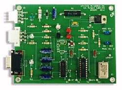
The MDB2PC™ now makes it possible to interface MDB vending devices to a PC:
Upstate Networks Incorporated
Products to interface vending devices to PCs since 1994.
[Order]
[Search]
[Technical
Support ] [Software] [Company Profile] [Contact us] [Home]
The MDB2PC™ now makes it possible to interface MDB vending devices to a PC: |
|
MDB2PC™ FAQ’s
A. Any device that is MDB compliant can be used with the MDB2PC™.
Q.
What are the power requirements for the MDB2PC™?
A. The MDB2PC™ works within the MDB specified voltage of 20-42VDC. Depending on what devices are connected you may need a power supply capable of 6 amps.
Q. What are the Mode Select Jumpers used for?
A. The Mode Select Jumpers are used to configure the MDB2PC™ for different bill validator manufacturers and for selecting between Operational Mode or HyperTerminal Mode.
Mode Select Jumper 1 – Selects between Operational Mode (Jumper OFF) and Hyperterminal Mode (Jumper ON). Note: When HyperTerminal Mode is selected the PC can NOT send data to the MDB2PC. This setting disables the handshaking between the PC and MDB2PC™.
Mode Select Jumper 2 – Selects between Coinco Bill Validators (Jumper ON) and other brand devices (Jumper OFF)
Q. Where can I find the codes sent from the MDB devices?
A. The codes sent from the devices can be view in Hyperterminal. Set Mode Select Jumper 1 to the ON position. Open HyperTerminal (9600, 8, none, 1) and start the MDB2PC™ with the devices connected. Operate the device and the codes will be displayed on the PC. Note: You can not send commands to the devices through the PC while in HyperTerminal.
Q. When I send a command to the MDB2PC™ from the PC nothing happens. What Am I doing wrong?
A. When the PC has data to send to an MDB device the following is required for sending this data.
Send DTR high (DTR.enabled=TRUE)
On Change (toggle) in CTS line (generated by the
MDB2PC™) set output buffer=string to be transmitted.
Place
contents of string in output buffer and transmit
Set DTR low after transmitting the entire string.
A. See Below
This command will reset the coin changer to its default operating mode. It will abort all communication and disable all acceptance until otherwise instructed.
Indicates the feature level of the changer.
Level 2: Supports
“core” commands. These are RESET, STATUS, TUBE
STATUS, COIN TYPE, and DISPENSE
Level 3: Supports level 2 and the Expansion Command
Z2
– Z3 =
Country Code – 2 bytes
The International Telephone Code that the changer is setup for.
Z4
=
Coin Scaling Factor – 1 byte
All accepted coin values are divisible by this number.
Z5
=
Decimal Places – 1 byte
Indicates number of decimal places on a credit display.
Z6
- Z7 =
Coin Type Routing – 2 bytes
Indicates what coin types can be routed to the changer tubes.
b15, b14, b13, b12, b11, b10, b9,
b8 |
b7, b6, b5,
b4, b3,
b2, b1,
b0
Z6
Z7
A bit is set to indicate a coin type can be routed to a tube.
Z8
– Z23 =
Coin Type Credit – 16 bytes
TUBE
STATUS 0AH Response
18 bytes: Z1 – Z18
Indicates status of coin tube for coin types 0 to 15.
b15, b14, b13, b12, b11, b10, b9,
b8 |
b7, b6, b5,
b4, b3,
b2, b1,
b0
Z1
Z2
A bit is set to indicate a full tube.
Z3
– Z18 =
Tube Status – 16 bytes
Indicates the greatest number of coins that the
changer definitely knows are present in the coin tubes. A bytes position in the
16 byte string indicates the number of coins in a tube for a particular coin
type. The first byte sent indicates the number of coins in a tube for coin type
0. Unsent bytes are assumed to be zero.
Note: If a changer can detect a tube jam, defective
sensor, or other malufunction, it will indicate the tube is bad by sending a
tube full status and a count of zero for that tube.
To dispense a coin or series of coins from the PC you must send the dispense command (0DH) followed by 1byte of data consisting of the coin type and number of coins to dispense.
Y1
=
Coin Types Dispensed -
1 byte
Bits b3,b2,b1,b0 indicate coin type to be dispensed.
Bits
b7,b6,b5,b4 indicates the number of coins to be dispensed.
b7 b6 b5
b4 |
b3 b2 b1
b0
Y1
Example:
If you wanted to dispense 5 of coin type 2 you would
send the string: 0DH 52H
COIN
TYPE 0CH
Followed by 4 bytes: Y1 - Y4
This command is used for enabling and disabling the coin types accepted and manually dispensed.
Y1
– Y2 =
Coin Enable - 2 bytes
A bit is set to indicate a coin type is accepted. Bit
5 is set to indicate coin type 5, bit 14 is set to indicated coin type 14. The
changer can be disabled by clearing all bits (0000H).
b15 b14
b13 b12
b11 b10
b9 b8
| b7 b6
b5 b4
b3 b2 b1
b0
Y1
Y2
Y3
– Y4 =
Manual Dispense Enable -
2 bytes
A bit is set to indicated manual dispense enable. Bit
3 is set to enable manual dispensing of coin type 3 and so on. All manual
dispensing switches are enabled upon power up or reset.
b15
b14 b13
b12 b11
b10 b9 b8 |
b7 b6
b5 b4 b3
b2 b1
b0
Y3
Y4
Example:
If you wanted to be able to manually dispense coin
types 3 and 9 and be able to accept all coin types except for type 5 you would
send the command string: 0CH FFH
DFH 02H 08H
Before trying to use the Level 3 commands you must have Coinmech with Level 3 command support.
All the expansion commands start with the code OFH and are followed by several different sub-commands (00H – 04H).
Identification code for the equipment supplier.
Z4
– Z15 =
Serial Number - 12 bytes
Factory assigned serial number.
Z16
– Z27 =
Model#/Tuning Revision – 12 bytes
Manufacturer assigned model number and tuning number.
Z28
– Z29 =
Software Version – 2 bytes
Current Software Version
Z30
– Z33 =
Optional Features – 4 bytes
b31, b30, b29, b28, b27, b26, b25,
b24 … b7, b6, b5, b4, b3, b2, b1, b0
Z30
Z33
Each of the 32 bits indicate and optional featurw
availability. If the bit is set the feature is available.
b0 =
Alternate Payout Method
b1 – b31 = Avaiable for future use.
Currently the only available feature to enable is the “Alternate Payout Method”. For more info on the alternate payout method see “Payout (02H)” below.
To enable a feature a bit is set. Example: To enable
the Alternate Payout Method the last bit would be set (bit 0).
If supported by the device, this command will allow the coin changer to determine what coins to dispense for a given value. It will also dispense the least number of coins need to equal that value.
This value is expressed as the number of coin scaling
factors that would sum to the value. Example: USA system using a scaling factor
of 5, if the change to be paid out was 35 cents, then Y1 will equal 7.
This is the changers response to the last VMC payout command. Bytes are sent in ascending order of coin types. A bytes position in the string indicates the coin type. That is byte one is for coin type 1, etc.
ZZ1
=
Value of coins paid out since last time this command was sent. This value
is also reset each time a new 02H PAYOUT command is sent.
Bill Validator Commands
RESET
30H
The reset command is used to tell the validator that it should return to its default-operating mode. The validator will reject any bills in the validation process, escrow position, and disable all other activity until otherwise instructed.
This command is used to look at the status of the bill validator. Used sends a 31H and the Bill validator returns 27 bytes of data.
Z4
– Z5 = Bill Scaling Factor
- 2 bytes
All accepted bills must be divisible by this number.
Ex. US currency could
be set to 0064H (100 decimal).
Number of bills the stacker will hold. Example: 400
bill capacity = 0190H
Z9
– Z10 = Bill Security Levels -
2 bytes
Security level for bill types 0 to 15. Validators
with out multiple security levels must report a high security level.
Z11 = 00H – Bill validator does not have escrow capability.
Z11 = FFH – Bill validator has escrow ability.
Z12
– Z27 = Bill Type Credit - 16 bytes
Indicates the value of bill types 0 to 15. Values sent in ascending order.This
number is the bill’s monetary value divided by the scaling factor. Unused
bill types are sent as 00H.
BILL TYPE
34H
Followed by 4 bytes: Y1
– Y4
This
command is used to enable/disable the type of bills accepted and held in Escrow.
User sends 34H followed by 4 bytes of data.
Y1 – Y2 = Bill Enable – 2 bytes
Indicates what types of bills are accepted. Bill types are 0 to 15. A bit is set to indicate acceptance of bill type.
b15 b14 b13 b12 b11 b10 b9 b8 | b7 b6 b5 b4 b3 b2 b1 b0
Y1 Y2
Note: Sending 0000H disables the bill validator.
Y3 – Y4 = Bill Escrow Enable - 2 bytes
Bill types are 0 to 15. A bit is set to indicate enable of escrow for a bill type.
b15 b14 b13 b12 b11 b10 b9 b8 | b7 b6 b5 b4 b3 b2 b1 b0
Y3 Y4
Note: On power-up or RESET (30H) all bill acceptance and escrow are set to the MDB2PC™ default of all bills accepted, no bills held in escrow.
ESCROW
35H Followed
by 1 byte: Y1
This
command allows the user to manage the bill is escrow (accept or return bill).
The user sends 35H
followed
by 1 byte of data.
Y1 = Escrow Status - 1 byte
If
Y1 = 00H Return bill
in the escrow position.
If Y1 = 01H Stack the bill.
STACKER
36H Returns
2 bytes: Z1 – Z2
Indicates
stacker full condition and the number of bills in the stacker. User sends 36H
and the bill validator
returns
2 bytes of data
Byte 1 Byte2
Fxxx|xxxx xxxx|xxxx
F = 1 if the stacker is full, 0 if not.
xxxxxxxxxxxxxxx = The number of bills in the stacker.
EXPANSION
COMMAND 37H
subcommand - 00H
Returns 29 bytes Z1 – Z29
This
command is used for identification of the bill validator. Used sends 3700H,
validator responds with 29 bytes of data.
Z1 – Z3 = Manufacturer Code - 3 bytes
Manufacturer code currently defined by NAMA.
Z4 – Z15 = Serial Number - 12 bytes
Factory assigned serial number.
Z16 – Z27 = Model#/Tuning Revision - 12 bytes
Manufacturer assigned model number.
Z27 – Z29 = Software Version - 2 bytes
Current Software Version
Manufacturer Codes:
Coin Acceptors International (CoinCo) - CAI
Mars Electronics International - MEI
Up to eight (8) MDB compliant devices may be attached to a single MDB2PC™. The programming interface is user-friendly and may be downloaded for free. Sample source code is available and may be freely distributed. We also offer a Software Developer's Kit
Any MDB compliant device may be interfaced to a PC. This now makes it possible to accept and dispense any coin types including foreign currency and Euro Dollar (when available).
MDB compliant smart card readers can now be accessed.
Power requirements
24 to 35 Vdc
90 ma Typical
300 ma Maximum
Enviromental
Operating Temp 32°F to 158°F
0°C to 70°C
Storage Temp -22°F to 165°F
-30°C to 74°C
Relative Humidity 5% to 95% Non-condensing
Physical Weight
< 1 lb
Physical Dimensions
Length 4.0 inches Width 3.0 inches Height 1.1 inches
Connector Info
PWR 24-35V Pin 2 +24Vdc Nominal
Pin 4 Ground
MDB Pin 1 +24Vdc Nominal
Pin 2 Ground
Pin 3 N/C
Pin 4 MDB Receive Data
Pin 5 MDB Transmit Data
Pin 6 Common
RS-232 Pin 1 N/C
Pin 2 PC Transmit Data
Pin 3 PC Receive Data
Pin 4 DTR
Pin 5 Ground
Pin 6 N/C
Pin 7 N/C
Pin 8 CTS
Pin 9 N/C
LED/Jumper Designations
D2 +5Vdc
D3 MDB Activity
D4 PC Activity
D5 Status 1
D6 Status 2
Jmp1 Mode Select 1
Jmp2 Mode Select 2
Reliability
MTBF Actual TBD
Estimated 250,000 Hrs.
Contact us for pricing and availability at (315) 732-5664