Introduction
The latest version of MDB2PC™ User’s Guide, along with technical support and information about Upstate Networks, may be found on the Upstate Networks World-Wide Web server at http://www.upstatenetworks.com/
Overview
The MDB2PC™ is a Computer Peripheral for interfacing vending machine protocol used by various devices including: Dollar Bill Validators, Coin Acceptors, Coin Dispensers, Smart Cards Foreign Currency etc.
This describes the Interface Protocol for the MDB2PC Hardware circuit. The MDB2PC™ interfaces any MDB vending device (6-pin molex/5pin MTA) to the PC via the serial port (DB-9) Future support may include Universal Serial Bus. The MDB2PC™ protocol is compatible with standard RS-232 Protocol.
System Requirements
MDB2PCÔ requires:
· An IBM PC compatible, with 486 or better processor.
· A serial COM port.
· An MDB compatible vending device
· External Power supply (Typically 24VDC)
· DB-9 (F-M)cable and MDB cable
License
MDB2PCä and MDBLABä copyright Ó1996-2000 by UNI. All rights reserved.
By using MDB2PC and MDBLAB, you agree to abide by the terms of this License to the best of your ability.
MDB2PCÔ is distributed free-of-charge for personal use by individuals and use by educational institutions. All others wishing to use MDB2PCÔ must obtain a site license from UNI. Licensing information is available by contacting UNI.
MDB2PCÔ must be distributed complete and intact without modifications whatsoever. No modifications are allowed, including BBS advertisements and modifications to the distribution .ZIP file. MDB2PCÔ may be distributed on BBS’s, Internet FTP sites, commercial online services, and on CD-ROM’s containing public domain, freeware, and shareware programs. In the case of CD-ROM distribution, notice must be given that the disc contains shareware with an explanation of the shareware concept, such as in the distribution notices required on the SimTel and Garbo CD-ROM’s.
For permission to distribute MDB2PCÔ with a magazine, book, or bundled with another product contact UNI.
You agree you will not attempt to reverse compile, modify, translate, or disassemble MDB2PCÔ in whole or in part and that you will make reasonable efforts to prevent anyone from doing same.
You agree that you will allow UNI to contact you for purposes of announcing new releases, bug-fixes, and other technical and business information.
UNI warrants that MDB2PCÔ will perform substantially for a period of sixty (60) days from the date of license. Any implied warranties relating to MDB2PCÔ are limited to sixty (60) days.
If MDB2PCÔ does not conform to the limited warranty above, UNI’s entire liability and your sole and exclusive remedy shall be, at UNI’s option, either to (a) correct the error or (a) help you work around or avoid the error. The limited warranty is void if failure of MDB2PCÔ is due to accident, abuse, or misapplication, including use of MDB2PCÔ with beta-test or non-compliant operating systems and software. Any replacement will be warranted for the remainder of the original limited warranty period.
UNI does not warrant that MDB2PCÔ is error-free. Except for the express limited warranty above, UNI disclaims all other warranties with respect to the software, either express or implied, including but not limited to implied warranties of merchantability, fitness for a particular purpose, and noninfringement of third-party rights.
In the event of invalidity of any provision of this license, the parties agree that such invalidity shall not affect the validity of the remaining portions of this license.
In no event shall UNI be liable for consequential, incidental or indirect damages of any kind arising out of the delivery, performance or use of the software, even if UNI has been advised of the possibility of such damages. In no event will UNI's liability for any claim, whether in contract, tort or any other theory of liability, exceed the license fee paid for MDB2PC, if any.
This license will be governed by the laws of the State of New York as they are applied to agreements between New York residents entered into and to be performed entirely within New York. The United Nations Convention on Contracts for the International Sale of Goods is specifically disclaimed.
If MDB2PCÔ is acquired (i) for use by the DOD, use, duplication or disclosure by the Government is subject to the terms of this license unless superseded by 252.227-7013(c)(1)(ii) or (ii) for use by civilian agencies, use, reproduction, or disclosure is subject to the terms of this license unless superseded by 52.227-19.
The MDB2PCÔ User Guide makes reference to a number of copyrighted and trademarked products. Rather than point out each one individually, we will note here that they are copyrighted and trademarked by their respective holders.
Install the MDB2PC™ on a free serial port either 9 pin or 25 pin (adapter required for 25 Pin) and designate it COM2. Serial Port settings are 9600, 8, 1, none. Interrupt conflicts must be avoided.
Connect 24Vdc power and MDB connections (6-pin Molex). Apply power. Check for LED1 (Green) indicating power is OK.
Install and run SETUP.EXE from the MDBLAB directory on Disk or CD-ROM provided. Insert different dollar bill denominations, coins OR mag swipe etc. and check to see that they register in the MDBLAB™ program. If all currency is registered the HARDWARE INSTALLATION is complete. Proceed to SOFTWARE DEVELOPERS KIT.
Hardware Installation
Hardware Specifics
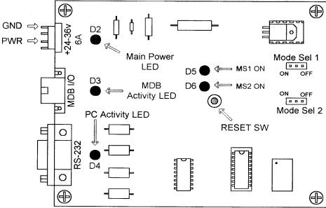
Figure 1 - Connector, Jumper, and LED locations
|
Mode Sel 1 |
Mode Sel 2 |
Function |
|
ON |
ON |
NORMAL OPERATION |
|
ON |
OFF |
FUTURE USE |
|
OFF |
ON |
FUTURE USE |
|
OFF |
OFF |
SELF DIAGNOSTIC |
Table 1 - Jumper functions
|
LED DESIGNATION |
INDICATION |
|
D2 |
+5 VDC |
|
D3 |
TRANSMIT TO MDB |
|
D4 |
TRANSMIT TO PC |
|
D5 |
FUTURE USE |
|
D6 |
FUTURE USE |
Table 2 - LED Functions
SPECIFICATIONS
Power requirements
24 to 35 Vdc
90 ma Typical
300 ma Maximum
Enviromental
Operating Temp 32°F to 158°F
0°C to 70°C
Storage Temp -22°F to 165°F
-30°C to 74°C
Relative Humidity 5% to 95% Non-condensing
Physical Weight
< 1 lb
Physical Dimensions
Length 4.0 inches Width 3.0 inches Height 1.1 inches
Connector Info
PWR 24-35V Pin 2 +24Vdc Nominal
Pin 4 Ground
MDB Pin 1 +24Vdc
Nominal
Pin 2 Ground
Pin 3 N/C
Pin 4 MDB Receive Data
Pin 5 MDB Transmit Data
Pin 6 Common
RS-232 Pin 1 N/C
Pin 2 PC Transmit Data
Pin 3 PC Receive Data
Pin 4 DTR
Pin 5 Ground
Pin 6 N/C
Pin 7 N/C
Pin 8 CTS
Pin 9 N/C
LED/Jumper Designations
D2 +5Vdc
D3 MDB Activity
D4 PC Activity
D5 Status 1
D6 Status 2 (DTR Active)
Jmp1 Mode Select 1
Jmp2 Mode Select 2
Install the MDB2PC™
It is time to install the MDB2PC™ itself and move on to the testing phase. Installation is relatively simple; there are only three connections that must be made for full functioning of the device. There are connectors on the edge of the board. One cable plugs into a 24VDC power supply. The 6-pin Molex connects to the MDB devices. The final connector is a DB-9 and connects into the back of the computer. There should be an open port on the back of the computer labeled “SERIAL2” or “COM2.”
Software
Overview
The MDB2PC sends information generated by the MDB device directly to the PC via RS-232 serial communication. There is no need to poll each MDB device. This is done by the MDB2PC. By default the MDB2PC will poll all known MDB devices. The MDB2PC then sends data to the PC if there is activity. The information sent to the PC is send as bytes in hexadecimal. The first byte sent is the device ID. For example 30 XX means that a bill validator has sent information. Whereas 08 XX means that a coin mechanism has sent data. Consult your manual for commands specific to your MDB device. We have included command sets for various CoinCo MDB devices in this document. Please note that all examples of source code are written in MS Visual Basic 5.0
MDB2PC Software Communication
Please visit our Download site at http://www.upstatenetworks.com/mdb/source.html for complete MDBLAB source code.
Receive
Use an interrupt driven comm event on the appropriate port. Settings are 9600-8-1-None. Set the receive threshold to 1. Empty the contents of the receive buffer as soon as there is at least one character ready. See the sample source code provided on CD-ROM for an example.
************************************************************************************************
Case comEvReceive
'Received RThreshold # of Chars
Do While comm_port.InBufferCount > 0
MDB2PC_input$ = comm_port.Input
‘MDB2PC_input$
is the output of the MDB to
the PC looking at the first five
‘characters
of MDB2PC_input$
‘enables the PC to determine current action of the MDB.
To look at the first five
‘characters of MDB2PC_input$, use Mid$(MDB2PC_input$, 1, 2)
b$ = Mid$(MDB2PC_input$, 1, 5) ' shorthand for looking at the first 5 characters
'The following are the typical actions produced by the MDB
If b$ = Mid$(MDB2PC_input$, 1, 2) = 50 Then
Label3.Caption = "Nickel
received"
nickins
= nickins + 1
RXSum = RXSum + 0.05
End If
************************************************************************************************
Use an interrupt driven comm event on the appropriate port. Settings are 9600-8-1-None. Set the transmit threshold to 1. Send the address of the device followed by the command parameters.
************************************************************************************************
Private
Sub Command6_Click()
MDB_output_string
= Chr$(13) & Chr$(&H52)
'Dispense Quarter
comm_port.DTREnable
= True 'Start Handshaking
End Sub
Case
comEvCTS
'Change in the CTS line
' this is the output routine for transmitting
' outbuffersize set to 32 bytes, SThreshold = 1
comm_port.Output = MDB_output_string
comm_port.DTREnable
= False
'END transmit one character on change of CTS line
*************************************************************************************************
When the PC has data to send to an MDB device the following is required for sending this data:
- Send DTR high (DTR.Enabled=TRUE)
- On Change in CTS line (generated by the MDB2PC) set output buffer=string to be transmitted
- Place contents of string in output buffer and transmit
- Set DTR low after transmitting entire string
UNI offers technical support for MDB2PCÔ primarily by e-mail.
Please read this manual thoroughly before contacting UNI.
Technical support is available via e-mail 24-hours-a-day, 7-days-a-week at tech@upstatenetworks.com.
|
|
Priority support will be given to people who have followed the instructions in the Before Contacting Technical Support section below. |
Before Contacting Technical Support
When contacting technical support with a question, please have the following information available or enclosed with your e-mail:
· your name, e-mail address, fax and telephone number
· MDB2PCÔ version number
· a detailed description of the problem you are experiencing
· computer software type (operating system name and version, brand and version of other network drivers, video driver settings, plus the name and version of any device drivers or other memory-resident programs)
· computer hardware type (type and make of CPU, RAM, hard disk type and size, video and network cards installed plus any other unusual cards)
MDB OPERATION NOTES
BILL VALIDATOR
Bills Accepted (Byte 1)
1yyyxxxx yyy = Bill Routing
000 = Bill Stacked
001 = Escrow Request
010 = Bill Returned
011 = Not Used
100 = Disabled Bill Rejected
xxxx = Bill Type
The bill types are:
Type 0 = $1 Type 2 = $5 Type 4 = $20
Type 1 = $2 Type 3 = $10
The bill type number is also the same as the bit # that must be set in order to enable the acceptance of the bill itself. Ex. Set bit 3 to enable acceptance of a $10.
When all of the DIP switches, on the BV, are set to NOT accept any type of bill, the validator’s default is to accept one dollar bills.
The software should have all of the bill types enabled, this will allow the user to set which type of bills to be accepted on the validator itself.
Bill Validator Operation Notes
-Firmware sets Bill Validator to accept 1, 2, 5, 10, 20 US bills by default
-Any commands to changed bills accepted or held in escrow will be set back to the firmware defaults upon a cycling of power or reset.
VMC Commands for Bill Validator
US Bills – Bit 0 = $1 Bit 3 = $5 Bit 5 = $20
Bit 1 = $2 Bit 4 = $10
BILL’S ACCEPTED
Bill Type 34h 4bytes Y1-Y4
Bill’s Accepted
Y1-Y2 = 001Fh for all US bills accepted
= 0000h accept no bill’s
Bill’s held in Escrow
Y3-Y4 = 001Fh for all US bills held in escrow
= 0000h for no bill’s held in escrow
Send out 34h and then the 4 bytes Y1-Y4 to change bill’s accepted and held in escrow.
BILL’S IN ESCROW ACTION
Escrow 35h 1byte Y1
Return bill Y1 = 00h
Stack bill Y1 = 01h
Send 35h and then Y1 to act on bill held in escrow
STACKER STATUS
Stacker 36h response Z1-Z2
Byte1 Byte2
Fxxxxxxx xxxxxxxx
F=1 Stacker Full
Xxxxxxxxxxxxxxx = Number of bill’s in stacker
Send out a 36h to the Bill Validator—It will respond with 2 bytes Z1-Z2
BILL VALIDATOR |
|
|
All values are in hex |
MDB data from Bill Validator to the PC |
|
|
|
Bill Accepted |
|
|
$1 |
89 |
|
$2 |
8A |
|
$5 |
8B |
|
$10 |
8C |
|
$20 |
8D |
Bill Returned |
All valid bill types disabled in software |
|
$1 |
C9 |
|
$2 |
CA |
|
$5 |
CB |
|
$10 |
CC |
|
$20 |
CD |
Bill Held In Escrow |
|
|
$1 |
99 |
|
$2 |
9A |
|
$5 |
9B |
|
$10 |
9C |
|
$20 |
9D |
Bill forcibly Removed |
|
|
$1 |
B0 |
|
$2 |
|
|
$5 |
|
|
$10 |
B3 |
|
$20 |
B4 |
Bill Validator Status |
|
|
01 |
Defective Motor |
|
02 |
Sensor Problem |
|
03 |
Validator Busy |
|
04 |
ROM Checksum Error |
|
05 |
Validator Jammed |
|
06 |
Validator was Reset |
|
07 |
Bill Removed |
|
08 |
Cash Box Out of Position |
|
09 |
Unit Disabled |
|
0A |
Invalid Escrow Request |
|
0B |
Bill Rejected |
|
010xxxxxx |
Number of attempts to input a bill while validator is disabled |
|
14 |
Bill not accepted either because the bill type is not enabled in the software or the bill was not recognized. |
COIN ACCEPTOR
Coins
Deposited: (Byte 1)
(Byte 2)
01yyxxxx
yy = Coin
Routing
zzzzzzzz = The number of coins
00: Cash Box
in the tube for the
01: Tubes
type accepted.
10: Not Used
11: Reject
xxxx = Coin
Type
Coins
Dispensed Manually
(Byte 2)
1yyyxxxx
yyy = The number of coins dispensed
zzzzzzzz = Same as above.
xxxx = The coin type dispensed
The coin types are:
Type
0 = 5c
Type 2 = 25c
Type 5 = $2 Can.
Type
1= 10c
Type 4 = $1 Can.
Note: The type of the coin is the same as the bit that needs to be set in the ‘mdbCointype’ routine in order to enable the acceptance, or distribution of that coin.
COIN ACCEPTOR |
||||
|
All values are in hex. |
DATA RECEIVED FROM MDB AND SENT TO THE PC |
|||
Below Low Mark |
Above Low Mark |
Above High Mark |
||
Coin Inserted |
|
|||
|
NICKEL |
50 |
56 |
8C |
|
|
DIME |
51 |
59 |
AC |
|
|
QUARTER |
52 |
58 |
8D |
|
|
QUARTER (1) |
||||
|
$1 CANADIAN* |
||||
|
$2 CANADIAN* |
||||
|
* Dollar coins are routed directly to the cash box |
||||
Coin Dispensed Manually |
|
|||
|
NICKEL |
90 |
96 |
DC* |
|
|
DIME |
91 |
99 |
FC |
|
|
QUARTER |
92 |
98 |
DD |
|
|
QUARTER (1) |
92 |
98 |
A7 |
|
Coin Rejected |
|
|||
|
NICKEL |
76 |
BC |
||
|
DIME |
71 |
79 |
DC* |
|
|
QUARTER |
72 |
78 |
BD |
|
|
QUARTER (1) |
72 |
78 |
87 |
|
|
$1 CANADIAN |
74 |
|||
|
$2 CANADIAN |
75 |
|||
|
|
||||
MDB STATUS |
|
|||
01
|
Escrow Request |
|||
02
|
Changer Payout Busy |
|||
03
|
No Credit |
|||
04
|
Defective Tube Sensor |
|||
05
|
Double Arrival |
|||
06
|
Acceptor Unplugged |
|||
07
|
Tube Jam |
|||
08
|
ROM Checksum Error |
|||
09
|
Coin Routing Error |
|||
0A
|
Changer Busy |
|||
0B
|
Changer was Reset |
|||
0C
|
Coin Jam |
|||
21
|
Coin not recognized/slug. Returned. |
|||
Upon startup one of these values
below may be sent to the PC – These are the VMC Commands. Probably
ignore.
|
||||
08
|
Reset |
|||
09
|
Status |
|||
0A
|
Tube Status |
|||
0B
|
Poll |
|||
0C
|
Coin Type |
|||
0D
|
Dispense |
|||