|
The PC2MDB™
PC2MDB allows the
PC to act as a slave device for existing vending machine controllers (VMC). It
allows the PC to act as a cashless device. The PC2MDB interfaces any MDB
vending device to the PC via the serial port.. Perfect for PC interfaces to
existing vending machines to allow the PC to control the vending machine.
The PC2MDB™ is
available in several different packages to meet the needs of developers and
vending machine owners. Find out which package best meets your needs
here
Overview
The PC2MDB is a slave device
for an already existing vending machine with a vending machine controller (VMC).
It allows the PC to act as a cashless device and add credit(s) to the vending
machine. Special versions allow the PC to act as a bill validator or coin
acceptor/dispenser. By default the PC2MDB acts as device type 10 (cashless
device)
This describes the Interface
Protocol for the PC2MDB Hardware circuit. The PC2MDB™ interfaces any MDB vending
device (6-pin molex/5pin MTA) to the PC via the serial port (DB-9) Future
support may include Universal Serial Bus. The PC2MDB™ protocol is compatible
with standard RS-232 Protocol.
PC2MDB™ requires:
An IBM PC compatible, with 486 or better
processor.
A serial COM port.
An MDB compatible
vending device
External Power supply
(Typically 24VDC)
DB-9 (F-M) cable and MDB cable
|
Switch # |
|
Function |
|
1 |
OFF |
Operational Mode |
|
ON |
Ignore DTR |
|
2 |
OFF |
5
Second Start-up delay |
|
ON |
250
mSec start-up delay |
|
3 |
OFF |
5 mSec
Response time |
|
ON |
1
mSec Response time |
|
4 |
OFF |
440
uSec Inter-byte delay |
|
ON |
900
uSec Inter-byte delay |
|
|
|
|
|
|
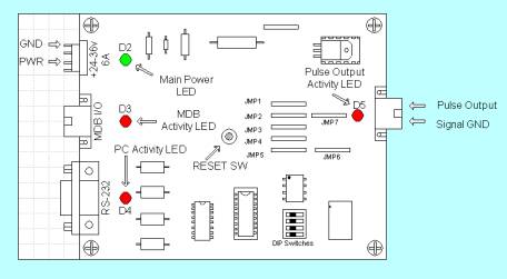
LED DESIGNATION |
INDICATION
|
|
D2 |
+5 VDC |
|
D3 |
TRANSMIT TO MDB |
|
D4 |
TRANSMIT TO PC |
|
D5 |
PULSE OUTPUT |
Table 2 - LED
Functions
|
JUMPERS |
INDICATION
|
|
JMP1 |
MDB2PC RD |
|
JMP2 |
PC2MDB RD |
|
JMP3 |
MDB2PC TX |
|
JMP4 |
PC2MDB TX |
|
JMP5 |
Not used |
|
JMP6 |
PULSE OUTPUT |
|
JMP7 |
NOT IN WHEN JMP6 IS IN
SPECIFICATIONS |
Power requirements
24
to 35 Vdc
90 ma Typical
300 ma Maximum
Environmental
Operating Temp 32°F to 158°F
0°C to 70°C
Storage Temp -22°F to 165°F
-30°C to 74°C
Relative Humidity 5% to 95% Non-condensing
Physical Weight
< 1 lb
Physical Dimensions
Length 3.5 inches Width 2.4 inches Height 1.5 inches
Mounting Template
Click here for template
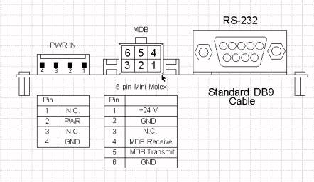
Connector Info
PWR 24-35V Pin 2 +24Vdc Nominal
Pin 4
Ground
MDB Pin
1 +24Vdc Nominal
Pin 2
Ground
Pin 3 N/C
Pin 4 MDB Receive Data
Pin 5 MDB Transmit Data
Pin 6 Common
RS-232 Pin 1 N/C
Pin 2 PC Transmit Data
Pin 3 PC Receive Data
Pin 4 DTR
Pin 5 Ground
Pin 6 N/C
Pin 7 N/C
Pin 8 CTS
Pin 9 N/C
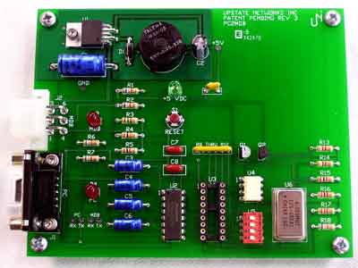
LED/Jumper Designations
D2 +5Vdc
D3 MDB Activity
D4 PC Activity
D6 Pulse Output Activity
Switch 1: Mode Select 1
Switch 2: Mode Select 2
It is time to install the
PC2MDB™ itself and move on to the testing phase.
Installation is relatively simple; there are only three connections that must be
made for full functioning of the device. There are
connectors on the edge of the board. One cable plugs into a
24VDC power supply. The 6-pin Molex connects to the VMC. The
final connector is a DB-9 and connects into the back of the computer.
There should be an open port on the back of the computer labeled
“SERIAL2” or “COM2.”
When the master/VMC has data to send we check
the mode bit to differentiate between ADDRESS bytes and DATA bytes. The upper
five bits (MSB) of the Address Byte are used for addressing. The lower three
bits of the Address Byte contain peripheral specific commands. This will allow
up to eight instructions to be embedded in the first byte of block.
The PC2MDB sends information generated by the
VMC device directly to the PC via RS-232 serial communication. It responds to
polls issued by the VMC. PC2MDB will ACK only the polls, and commands issued to
correct addresses. The PC2MDB then forwards the commands to the PC. Once the
data has been processed, the PC sends back another set of instructions to the
PC2MDB, which forwards these instructions to the VMC only when desired
poll/polls have been received. The information sent to the PC is send as bytes
in hexadecimal. The first byte sent is the device ID. For example 30 XX means
that a bill validator has sent information. Whereas 08 XX means that a coin
mechanism has sent data. Consult your manual for commands specific to your MDB
device. We have included command sets for various MDB devices in this
document. Please note that all examples of source code are written in MS Visual
Basic 5.0
PC2MDB Software Communication (vb.net)
| Import |
|
| |
Imports System.IO.Ports |
| Declare |
|
| |
Dim comPort as new SerialPort() |
| Open |
|
| |
//configure port
With comPort
.BaudRate = "9600"
.DataBits = "8"
.Parity = Parity.None
.StopBits = StopBits.One
.ReceivedBytesThreshold = 1
.DtrEnable = True
.PortName = portName
.Handshake = Handshake.None
.ReadBufferSize = 1024
.WriteBufferSize = 512
End With
//make sure port is closed before attempting //to open
If (comPort.IsOpen = True) Then
comPort.Close()
End If
//open port
Try
comPort.Open()
Catch ex As Exception
msgbox(Err.Number & ", " & Err.Description)
End Try
|
| |
|
| Receive Data |
|
| |
Private Sub comPort_DataReceived(ByVal_ sender As Object, ByVal e As_ SerialDataReceivedEventArgs)
Try
Dim tmp As String = ""
If comPort.BytesToRead > 0 Then
tmp = comPort.ReadExisting()
mdbInput = tmpD
End If
Catch ex As Exception
msgbox(Err.Number & ", " & Err.Description)
End Try
End Sub
|
| |
|
| Transmit Data |
|
| |
//transmit hex values in binary
// Begin Session Command with $2USD funds //(0x03 0x00 //0x28)
Try
comPort.Write(ChrW(&H3) & ChrW(&H0) & ChrW(&H64))
Catch ex As Exception
msgbox(Err.Number & ", " & Err.Description)
End Try
|
| |
|
|