The PLUM INTM
 User's Guide
Version 1.0
Payment Layer for Unattended
Merchandising TM
Upstate Networks Inc.
1001 Broad Street
Utica, New York 13501 USA
Image Coming Soon…
(315)
732-5664
info@upstatenetworks.com
www.upstatenetworks.com
Table of cONTENTS
Overview................................................................................... 3
Hardware Installation.................................................. 4
Hardware Specifics for PLUM IN................................................................. 4
Figure 1 - Connector, Switches, and LED locations...................... 4
Technical Support............................................................ 8
MDB Operation Notes....................................................... 9
BILL VALIDATOR...................................................................................................... 10
Bill Validator Operation Notes............................. 10
VMC Commands for Bill Validator......................... 10
Bills Accepted................................................................... 10
Bill Type... 34h 4bytes Y1-Y4......................................................................... 10
Bills held in Escrow......................................................................................... 10
Bills In Escrow Action.................................................. 11
Stacker Status................................................................. 11
BILL VALIDATOR..................................................................... 11
MDB data from Bill Validator to the PC........................................... 11
Bill Accepted............................................................................................................. 11
Bill Returned............................................................................................................. 12
All valid bill types disabled in software....................................... 12
Bill Held In Escrow.................................................................................................. 12
Bill forcibly Removed.............................................................................................. 12
Bill Validator Status............................................................................................... 12
Defective Motor........................................................................................................ 12
Sensor Problem........................................................................................................ 12
Validator Busy.......................................................................................................... 13
ROM Checksum Error............................................................................................. 13
Validator Jammed.................................................................................................... 13
Validator was Reset................................................................................................. 13
Bill Removed............................................................................................................. 13
Cash Box Out of Position....................................................................................... 13
Unit Disabled............................................................................................................ 13
Invalid Escrow Request.......................................................................................... 13
Bill Rejected.............................................................................................................. 13
Number of attempts to input a bill while validator is
disabled...................... 13
Bill not accepted either because the bill type is not
enabled in the software or the bill was not recognized. 13
Coin Acceptor..................................................................... 14
COIN ACCEPTOR........................................................................................................ 14
DATA RECEIVED FROM MDB AND SENT TO THE PC................................... 15
Below Low Mark...................................................................................................... 15
Above Low Mark...................................................................................................... 15
Above High Mark..................................................................................................... 15
Coin Inserted............................................................................................................ 15
Coin Dispensed Manually...................................................................................... 15
Coin Rejected........................................................................................................... 15
MDB STATUS............................................................................ 16
Escrow Request........................................................................................................ 16
Changer Payout Busy............................................................................................. 16
No Credit................................................................................................................... 16
Defective Tube Sensor............................................................................................. 16
Double Arrival.......................................................................................................... 16
Acceptor Unplugged............................................................................................... 16
Tube Jam.................................................................................................................... 16
ROM Checksum Error............................................................................................. 16
Coin Routing Error................................................................................................. 16
Changer Busy........................................................................................................... 16
Changer was Reset.................................................................................................. 16
Coin Jam.................................................................................................................... 16
Coin not recognized/slug. Returned.................................................................... 16
Reset........................................................................................................................... 17
Status.......................................................................................................................... 17
Tube Status................................................................................................................ 17
Poll............................................................................................................................. 17
Coin Type.................................................................................................................. 17
Dispense..................................................................................................................... 17
DESIGNED
BY:
Rob Smith
|
Revision
|
Date
|
Description
|
Written by
|
Approved By
|
|
1
|
9/17
|
Initial
Release
|
Rob
Smith
|
|
|
|
|
|
|
|
|
|
|
|
|
|
Introduction
The latest version of
PLUM IN TM User’s Guide, along with technical support and
information about Upstate Networks, may be found on the Upstate Networks
World-Wide Web server at http://www.upstatenetworks.com/.
The PLUM IN TM HAT is a device which is used
in conjunction with a Raspberry Pi to interface the multi-drop bus (MDB) vending
machine protocol used by various devices including: Dollar Bill Validators, Coin Acceptors, Coin
Dispensers, Smart Cards, Foreign Currency, etc.
This describes the Interface Protocol for
the PLUM IN TM HAT Hardware circuit. The PLUM IN
TM interfaces any MDB vending device (6-pin molex) to a Raspberry Pi.
System
Requirements
PLUM IN TM
requires:
·
A Raspberry Pi 3
·
A Multi-Drop bus(MDB) compatible
vending device (Bill Validator, Coin
Mechanism, etc.)
·
External Power supply
(Typically 24VDC)
·
MDB Y-cable
Install the PLUM IN Hat on a Raspberry Pi with Raspbian
OS.
(Serial Port settings
are 9600, 8, 1, none)
Connect 24Vdc power to
the PLUM IN TM via the 4 pin connector labeled J2. Using an MDB
Y-Cable, connect one of the 2 female connectors to the 6-pin male Molex MDB
connector labeled U3. Connect an MDB device (Bill Validator, Coin Accepter) to
the spare female connector on the MDB Y-Cable. Apply power. Check for LED1 (Green) indicating power is
OK. You should also hear the MDB device cycle on power up.
Hardware Specifics for PLUM IN
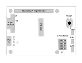
Figure 1 -
Connector, Switches, and LED
location
|
DIP SW
1
|
DIP SW
2
|
Function
|
|
OFF
|
OFF
|
5 Second Start-up delay/Operational Mode
|
|
ON
|
OFF
|
5 Second Start-up delay / Ignore DTR
|
|
OFF
|
ON
|
250 mSec start-up delay / Operational Mode
|
|
ON
|
ON
|
250 mSec start-up delay / Ignore DTR
|
|
LED DESIGNATION
|
INDICATION
|
|
D3
|
+5 VDC
|
|
D1
|
TRANSMIT TO MDB
|
|
D2
|
TRANSMIT TO Rpi
|
SPECIFICATIONS
Power requirements
24 to 35 Vdc
90 ma Typical
300 ma Maximum
PLUM Power
5Vdc
3A Maximum
Environmental
Operating Temp 32°F to 158°F
0°C to 70°C
Storage Temp -22°F to 165°F
-30°C to 74°C
Relative Humidity 5% to 95% Non-condensing
Physical Weight
< 1 lb
Physical Dimensions
Length 85 mm Width 56.5 mm Height 1 mm
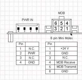
Connector Info
PWR Connector
J2
Pin 2 +24Vdc Nominal
Pin 3 Ground
MDB Connector J1
Pin 1 +24Vdc Nominal
Pin 2 Ground
Pin 3 N/C
Pin 4 MDB Receive Data
Pin 5 MDB Transmit Data
Pin 6 Common
LED Designations
D3 +5Vdc
D1 MDB
Activity
D2
RASPBERRY PI Activity
MDB/PWR IN Pin
outs
New Hardware Setup
Step1:
v
Update Raspbian Jessie
to the latest version by opening a command prompt and typing the following:
Ø sudo apt-get update
v
Wait for the update to complete then type the
following:
Ø sudo apt-get upgrade
v
The update may take over 5 minutes to complete.
Step 2:
v
Using a command prompt, type the following:
Ø sudo nano
/boot/cmdline.txt
v
Find the section of the string containing
“console = serial0,115200” and delete it. Click ctrl+x and type y then press enter twice.
Step 3:
v
Using a command prompt, type the following:
Ø sudo raspi-config
v
Locate advanced settings and select it. Then,
click serial and select “enable”
Step 1:
v
Create a folder named “PLUM_Apps”
in the /home/pi directory.(If folder already exists, skip this step)
Ø Copy
and paste the “PLUM_IN” folder as well as the “PLUM_IN_Utility”
script file to the “PLUM_Apps” folder.
Step 2:
v
In the “PLUM Apps” folder, right click on the “PLUM_IN_Utility” file and click properties.
Ø Click
the permissions tab and select Anyone under the
Execute selection box then click Ok.
Step 3:
v
In the “PLUM_Apps”
folder, double click on the “PLUM_IN” folder.
Ø Scroll
down until you see the “PLUM_IN_utility” icon.
§
Right click and select properties.
·
Click the permissions tab and select “Anyone”
under the Execute selection box and click ok.
Step 4:
v
To open the PLUM IN Utility, simply double click
on the “PLUM_IN_Utility” icon and click execute.
Technical Support
UNI
offers technical support for PLUM INÔ and
MDB2USB™ primarily by e-mail and at
http://www.upstatenetworks.com
 Please
read this manual thoroughly before contacting UNI.
Please
read this manual thoroughly before contacting UNI.
Technical
support is available via e-mail 24-hours-a-day, 7-days-a-week at info@upstatenetworks.com.
|
|
Priority
support will be given to people who have followed the instructions in the Before Contacting Technical Support section below.
|
MDB Operation Notes
Bills Accepted (Byte 1)
1yyyxxxx yyy = Bill
Routing
000 = Bill Stacked
001 = Escrow
Request
010 = Bill Returned
011 = Not Used
100 = Disabled Bill
Rejected
xxxx = Bill
Type
The bill types
are:
Type 0 = $1 Type 2 = $5 Type 4 = $20
Type 1 = $2 Type 3 = $10
The bill type number
is also the same as the bit # that must be set in order to enable the
acceptance of the bill itself. Ex. Set bit 3 to enable acceptance of a $10.
When all of the DIP
switches on the BV are set to NOT accept any type of bill, the validator’s default is to accept one dollar bills.
The software should
have all of the bill types enabled; this will allow
the user to set which type of bills to be accepted on the validator
itself.
-Firmware sets Bill
Validator to accept 1, 2, 5, 10, 20 US bills by default
-Any commands to
changed bills accepted or held in escrow will be set back to the firmware
defaults upon a cycling of power or reset.
US Bills – Bit 0 = $1 Bit 3 = $5 Bit 5 = $20
Bit 1 = $2 Bit 4 = $10
Bill’s Accepted
Y1-Y2 = 001Fh for all US bills accepted
= 0000h accept no bill’s
Y3-Y4 = 001Fh
for all US bills held in escrow
= 0000h for no bill’s held in escrow
Send out 34h and then
the 4 bytes Y1-Y4 to change bill’s accepted and held in escrow.
Bills In Escrow Action
Escrow 35h 1byte Y1
Return bill
Y1 = 00h
Stack bill Y1 = 01h
Send 35h and then Y1
to act on bill held in escrow
Stacker 36h response Z1-Z2
Byte1 Byte2
Fxxxxxxx xxxxxxxx
F=1 Stacker Full
Xxxxxxxxxxxxxxx
= Number of bill’s in stacker
Send out a 36h to the
Bill Validator—It
will respond with 2 bytes Z1-Z2
|
|
|
All values are in
hexadecimal
|
MDB data from Bill Validator to the PC
|
|
|
|
|
|
|
$1
|
30 80 09
|
|
$2
|
30 81 09
|
|
$5
|
30 82 09
|
|
$10
|
30 83 09
|
|
$20
|
30 84 09
|
|
|
|
|
$1
|
30 C0 09
|
|
$2
|
30 C1 09
|
|
$5
|
30 C2 09
|
|
$10
|
30 C3 09
|
|
$20
|
30 C4 09
|
|
|
|
|
$1
|
30 90 09
|
|
$2
|
30 91 09
|
|
$5
|
30 92 09
|
|
$10
|
30 93 09
|
|
$20
|
30 94 09
|
|
|
|
|
$1
|
30 A1 09
|
|
$2
|
30 A2 09
|
|
$5
|
30 A3 09
|
|
$10
|
30 A4 09
|
|
$20
|
30 A5 09
|
|
|
|
|
01
|
|
|
02
|
|
|
03
|
|
|
04
|
|
|
05
|
|
|
06
|
|
|
07
|
|
|
08
|
|
|
09
|
|
|
0A
|
|
|
0B
|
|
|
010xxxxxx
|
|
|
14
|
|
Coins
Deposited: (Byte 1) (Byte 2)
01yyxxxx yy = Coin Routing
zzzzzzzz = The number
of coins
00: Cash Box in
the tube for the
01: Tubes type
accepted.
10: Not Used
11: Reject
xxxx = Coin Type
Coins
Dispensed Manually (Byte 2)
1yyyxxxx yyy = # of coins dispensed zzzzzzzz = Same as above.
xxxx = The coin
type dispensed
The coin types are:
Type 0 = 5c Type
2 = 25c Type 5 = $2 Can.
Type 1= 10c Type
4 = $1 Can.
Note: The type of the coin is the same as the bit that
needs to be set in the ‘mdbCointype’ routine in order
to enable the acceptance, or distribution of that coin.
COIN ACCEPTOR
|
|
All values are in
hex.
|
|
|
|
|
|
Coin Inserted
|
|
|
NICKEL
|
08 50 00
|
08 50 06
|
08 40 4C
|
|
DIME
|
08 51 00
|
08 51 08
|
08 41 6B
|
|
QUARTER
|
08 52 00
|
08 52 06
|
08 42 4B
|
|
QUARTER (1)
|
08 52 00
|
08 52 06
|
08 42 15
|
|
$1 CANADIAN*
|
08 44 00
|
|
$2 CANADIAN*
|
08 45 00
|
|
* Dollar coins are
routed directly to the cash box
|
Coin Dispensed Manually
|
|
|
NICKEL
|
08 90 00
|
08 90 06
|
08 90 4C
|
|
DIME
|
08 91 00
|
08 91 08
|
08 91 6B
|
|
QUARTER
|
08 92 00
|
08 92 06
|
08 92 4B
|
|
QUARTER (1)
|
08 92 00
|
08 92 06
|
08 92 15
|
Coin Rejected
|
|
|
NICKEL
|
08 70 00
|
08 70 06
|
08 70 4C
|
|
DIME
|
08 71 00
|
08 71 08
|
08 71 6B
|
|
QUARTER
|
08 72 00
|
08 72 06
|
08 72 4B
|
|
QUARTER (1)
|
08 72 00
|
08 72 06
|
08 72 15
|
|
$1 CANADIAN
|
08 74 00
|
|
$2 CANADIAN
|
08 75 00
|
MDB STATUS
|
|
01
|
|
02
|
|
03
|
|
04
|
|
05
|
|
06
|
|
07
|
|
08
|
|
09
|
Coin Routing Error
|
0A
|
|
0B
|
|
0C
|
|
21
|
Coin not
recognized/slug. Returned.
|
Upon
startup one of these values below may be sent to the PC – These are the VMC
Commands.
|
08
|
|
09
|
|
0A
|
|
0B
|
|
0C
|
|
0D
|
|
|
|
|
|
|
INDEX