The PLUM OUTTM
 User's Guide
Payment Layer for Unattended Merchandising TM
Version 1.0
Image Coming Soon…
Upstate Networks Inc.
1001 Broad Street
(800) 369-5797
info@upstatenetworks.com
DESIGNED
BY:
Rob Smith
|
Revision |
Date |
Description |
Written By |
Approved
By |
|
1 |
9/17 |
Initial Release |
Rob Smith |
|
|
|
|
|
|
|
|
|
|
|
|
|
Introduction
The latest version of the PLUM OUT™ User’s Guide, along with technical support and information about Upstate Networks, may be found online at http://www.upstatenetworks.com/.
Overview
The PLUM OUT TM HAT is a device which works in conjunction with a Raspberry Pi with Raspbian OS to act as a cashless device when combined with any multi-drop bus (MDB) vending product. It is installed as a slave device for an already existing vending machine controller (VMC).
This document describes the Interface Protocol for the PLUM OUT™ hardware circuit. The PLUM OUT™ interfaces any MDB vending machine controller (VMC) to a Raspberry Pi via the 40 pin header(J1)
System
Requirements
·
A Raspberry Pi 3
(Also compatible with Rpi 2)
·
Raspbian OS installed
·
A multi-drop bus
(MDB) compatible
vending machine
·
MDB Y Cable
Install the PLUM OUT TM HAT at on a Raspberry Pi 3 with a Raspbian OS. (Serial Port settings are 9600, 8, 1, none.)
Connect the male 6-pin Molex MDB connector to the 6-pin Molex connector labeled U6 on the PLUM OUT TM HAT. Connect the second male 6-pin Molex MDB connector to the vending machine controller VMC. Apply power. Check for the power LED labeled D1 (Green) indicating power is OK.
Hardware Specifics for PLUM OUT TM
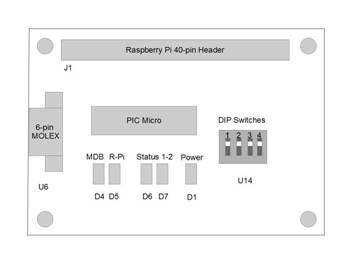
Figure 1 - Connector, Switches, and LED locations
|
|
OFF |
ON |
|
1 |
10H |
60H |
|
2 |
Level
1 |
Level
2/3 |
|
3 |
ASCII |
Binary |
|
ALL |
|
Self
Test |
|
LED DESIGNATION |
INDICATION |
|
D1 |
+5 VDC |
|
D4 |
MDB ACTIVITY |
|
D5 |
RASPBERRY PI ACTIVITY |
|
STATUS 1 |
|
|
D7 |
STATUS 2 |
Table 2 - LED Functions
PLUM OUT Option Selection
The four-position dip switch controls the selection of various configurable options these include the cashless device address, the cashless device level (1 or 2), ASCII or Binary transfer from the MDB to the Raspberry Pi and selftest.
Cashless Device Address
DIP Switch Position 1 controls the cashless device MDB address. If the switch is off the PLUM OUT board will respond to 10hex, the primary cashless device address. If the switch is on the PLUM OUT board will respond to 0x60, the secondary cashless device address.
DIP Switch Position 2 controls the cashless device level selection. If the switch is off the PLUM OUT board will identify itself as a level 1 cashless device If the switch is on the PLUM OUT board will identify itself as a level 2 cashless device.
ASCII
/ Binary Data Transmission
DIP switch position 3 controls ASCII or binary data transmission. If switch 3 is in the off position all data transferred from the MDB will be in HEX ASCII format. All ASCII strings are terminated by a CR/LF sequence. Binary data transmission, from the MDB to the Raspberry Pi, is selected by turning position 3 of the DIP switch to the on position. When switch #3 is on, all data from the MDB will be sent to the Raspberry Pi in its original 8 bit binary form. In order to define the length of the data string being sent to the Raspberry Pi, a length byte is added to the beginning of the string. The length count is a count of the total number of bytes sent including the length byte.
DIP switch position 4 is set to its default position
Self Test
All DIP switches set to ON invokes self test after reset.
SPECIFICATIONS
Power requirements
24 to 35 Vdc
90 ma Typical
300 ma Maximum
Environmental
Operating Temp 32°F to 158°F
0°C to 70°C
Storage Temp -22°F to 165°F
-30°C to 74°C
Relative Humidity 5% to 95% Non-condensing
Physical Weight
< 1 lb
Physical Dimensions
Length 65 mm Width 56.5 mm Height 1 mm
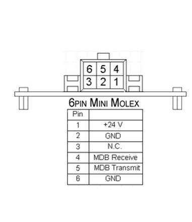
Connector Info
MDB
Pin 1 +24Vdc
Nominal
Pin 2 Ground
Pin 3 N/C
Pin 4 MDB Receive Data
Pin 5 MDB Transmit Data
Pin 6 Common
LED Designations (See Figure 1)
MDB PINOUT
PLUM OUT Utility Installation
New Hardware Setup
Step1:
v Update Raspbian Jessie to the latest version by opening a command prompt and typing the following:
Ø sudo apt-get update
v Wait for the update to complete then type the following:
Ø sudo apt-get upgrade
v The update may take over 5 minutes to complete.
Step 2:
v Using a command prompt, type the following:
Ø sudo nano
/boot/cmdline.txt
v Find the section of the string containing “console = serial0,115200” and delete it. Click ctrl+x and type y then press enter twice.
Step 3:
v Using a command prompt, type the following:
Ø sudo raspi-config
v Locate advanced settings and select it. Then, click serial and select “enable”
PLUM OUT Utility Setup
Step 1:
v Create a folder named “PLUM_Apps” in the /home/pi directory. (If folder already exists, skip this step)
Ø Copy and paste the “PLUM_OUT” folder as well as the “PLUM_OUT_Utility” script file to the “PLUM_Apps” folder.
Step 2:
v In the “PLUM Apps” folder, right click on the “PLUM_OUT_Utility” file and click properties.
Ø Click the permissions tab and select Anyone under the Execute selection box then click Ok.
Step 3:
v In the “PLUM_Apps” folder, double click on the “PLUM_OUT” folder.
Ø Scroll down until you see the “PLUM_OUT_utility” icon.
§ Right click and select properties.
· Click the permissions tab and select “Anyone” under the Execute selection box and click ok.
Step 4:
v To open the PLUM Picker Utility, simply double click on the “PLUM_OUT_Utility” icon and click execute.
Technical Support
UNI offers technical support for PLUM OUTÔ primarily by e-mail and at http://www.upstatenetworks.com.
Please read this manual thoroughly before contacting UNI.
Technical support is available via e-mail 24-hours-a-day, 7-days-a-week at tech@upstatenetworks.com.
|
|
Priority support will be given to people who have followed the instructions in the Before Contacting Technical Support section below. |
 Before Contacting
Technical Support
Before Contacting
Technical Support
When contacting technical support with a question, please have the following information available or enclosed with your e-mail:
Your name, e-mail address, fax and telephone number.
PLUM OUTÔ serial number (Located on the packaging material).
A detailed description of the problem you are experiencing.
Computer software type (operating system name and version, brand and version of other network drivers, video driver settings, plus the name and version of any device drivers or other memory-resident programs).
Computer hardware type (type and make of CPU, RAM, hard disk type and size, video and network cards installed plus any other unusual cards)
MDB Operation Notes
|
EXAMPLE VEND
SESSION #1* |
|
|
VMC=
Vending Machine Controller,
PLUM OUT=
Raspberry Pi to MDB interface,
Software= front end software or PLC |
|
|
VMC-10 |
(RESET) 10h |
|
PLUM OUT-00 |
(ACK) 00h Acknowledged |
|
VMC-11 00 |
(SETUP CONFIGURATION DATA)
11 00: To send the VMC's configuration
data and obtain the cashless device's data |
|
PLUM OUT-01 01 00 01 01 01 30 00 |
(PLUM OUT RESPONSE) 8 BYTES Z1-Z8 Z1: reader config
data (indicates the payment media reader is responding to a SETUP) 01H |
|
VMC-11 01 |
(SETUP MAX/MIN PRICE) 11 01: To send the maximum and minimum prices in
the VMC. These prices must
be sent as Level 01/02 16 bit credit |
|
PLUM OUT-01 FF FF
00 00 |
(PLUM OUT RESPONSE) 5 BYTES Y1-Y5 Y1: Max/Min prices. Indicates the VMC is sending the price range to the reader
(01H) |
|
VMC-17 00 |
(EXPANSION REQUEST ID) 17 00: To obtain additional cashless device
information and options |
|
PLUM OUT-00 55 4E 49 00 00 00 00 |
(PLUM OUT RESPONSE) 30 BYTES Y1-Y30 Y1: Request ID. The VMC is requesting payment media reader
identification information. The information included above (y2-Y30) provides
the payment media reader with VMC identification information. 00h |
|
VMC-14 01 |
(ENABLE) 14 01/(DISABLE) 14 00 |
|
PLUM OUT-00 |
(ACK) 00h Acknowledged |
|
VMC-12 |
(POLL) 12h |
|
PLUM OUT-00 |
(ACK) 00h Acknowledged |
|
SOFTWARE-03 |
(BEGIN SESSION) 03 The Programmer will
have to issue a BEGIN SESSION command (03h) which will be sent to the VMC on a poll. |
|
VMC-12 |
(POLL) 12h |
|
PLUM OUT-03 |
(POLL) 12h This is the value that was passed from the
RASPBERRY PI via the PLUM OUT indicating that the programmer wished to
begin a session. |
|
VMC-00 |
(ACK) 00h Acknowledged The VMC will ACK the BEGIN SESSION command |
|
VMC- 13 00 00 14 00 01 |
(VEND REQUEST) 13 00 The VMC issues a VEND REQUEST command (13 00 00 14 00 01h). The first two bytes 13 00 are vend
request. The VMC is requesting vend approval from the payment media
reader before dispensing the product. The next two bytes 00 14h are
scaled item price. This scaled item price is set by bytes Z5 and Z6 in
the reader response data for the MAX/MIN PRICES SETUP command. And the
last two bytes 00 01h are item selection number. |
|
PLUM OUT-00 |
(ACK) 00h Acknowledged. The vend request command will be ACKed |
|
VMC-12 |
(POLL) 12h |
|
VMC-12 |
(POLL) 12h |
|
SOFTWARE-05 |
(VEND APPROVED) 05 passed on to the programmer
to be approved with a VEND APPROVED command (05h) command |
|
VMC-12 |
(POLL) 12h |
|
PLUM OUT-05 |
(VEND APPROVED) 05 The vend approved command that was sent
from the RASPBERRY PI is relayed to the VMC via the PLUM OUT |
|
VMC-00 |
(ACK) 00h Acknowledged |
|
VMC-13 02 |
(VEND SUCCESS) 13 02 Once this command has
been received a VEND SUCCESS command (13 02h)
will be issued by the VMC,
and ACKed by the cashless device. |
|
PLUM OUT-00 |
(ACK) 00h Acknowledged |
|
VMC-13 04 |
(SESSION COMPLETE) 13 04 Upon the receiving of
an ACK, a SESSION COMPLETE command (13 04h) will be issued by the VMC and also ACKed by
the cashless device. |
|
PLUM OUT-00 |
(ACK) 00h Acknowledged |
|
VMC-12 |
(POLL) 12h |
|
PLUM OUT-07 |
(END SESSION) 07 In order to end a
vend session, and END SESSION command (07h) will have to be sent to the VMC on a poll by the end user. |
*[1].
National Automatic Merchandising Association, February, 2011. Multi_Drop Bus/Internal Communication Protocol: Section 7
"Cashless Device(s) VMC/Peripheral
Communication Specifications": 7.1-7.53.
INDEX